As my bluetooth headset seems to be a dead loss, I thought I’d take it apart to see how it was made. I did a lot of searching and I don’t think anyone has done this yet - I certainly couldn’t find any photos.
If you grab the plastic bit where the button is and wiggle it, you eventually break the glue and you can pull the whole plastic section out a bit.
There’s a really small rf plug and a small ribbon cable plug which you can unplug. Both wires lead to the earphone bit. The cover for the earphone can be pried off (it’s glued) to reveal a small circular circuit board.
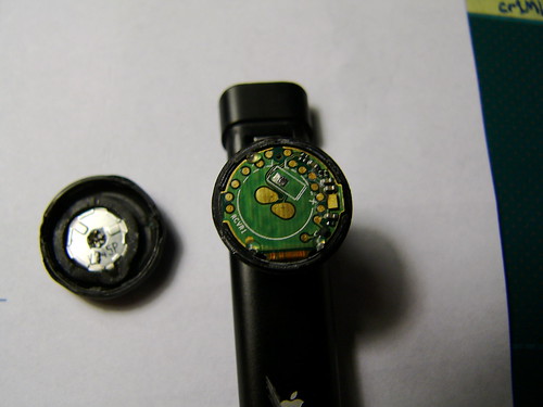
the circuit board can be lifted carefully to reveal another slightly smaller circuit board
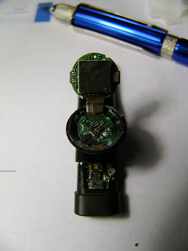
The two circuit boards are joined by a sticky foam pad. Cleaning it off reveals the markings on the chip
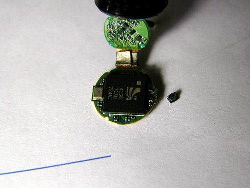
You can also see a small inductor which I managed to snap off the large circular circuit board when I was trying to lift it. D’oh.
Lifting the small circuit board reveals the two wires leading to the circuit board where the switch is

The rubbery sealant at the bottom can be scraped away, then the cables can be de-routed back through the hole and the two circular circuit boards set to one side

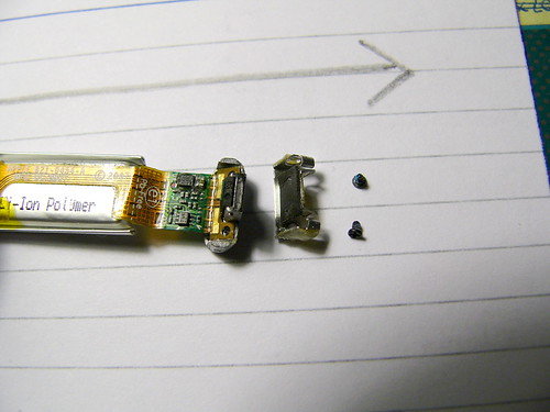
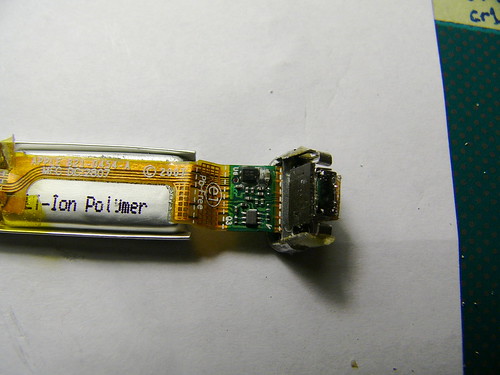
The rest of the circuitry is a lot harder to remove. There is a ribbon cable attached to the switch PCB which connects it to the battery, power / USB connector, and microphone. The connector is glued into the end of the can extremely well, and eventually I had to resort to a hacksaw to extract it. There is no way I can see to break remove the connector without destroying the headset. The glue is just too strong.
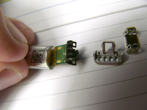
I realised later how I should have done this part of the job. When it is assembled in the factory, the components are threaded into the body of the headset from the switch end, without the metal connector attached to the end. The metal connector body is mated to the terminals with a couple of really small screws, then glue is applied and the connector is inserted into the end of the headset. So I still would have chewed up the end of the headset getting the connector out, but I wouldn’t have had to saw the whole headset apart to thread the circuit board back out. I didn’t take any photos of the sawn up headset because I was too embarrassed.
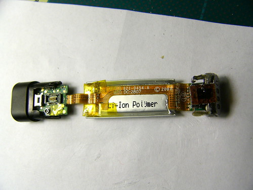
here’s the battery and the rest of the circuitry
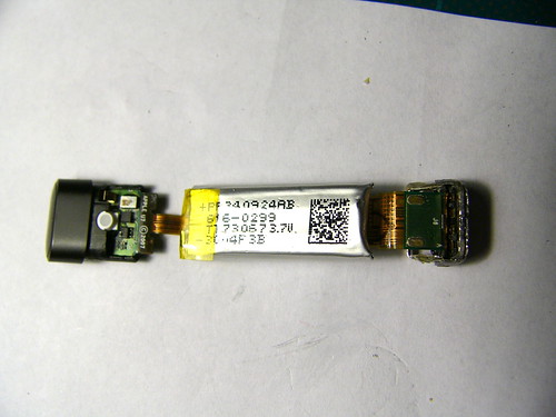
The circuit board is marked “Pb Free”
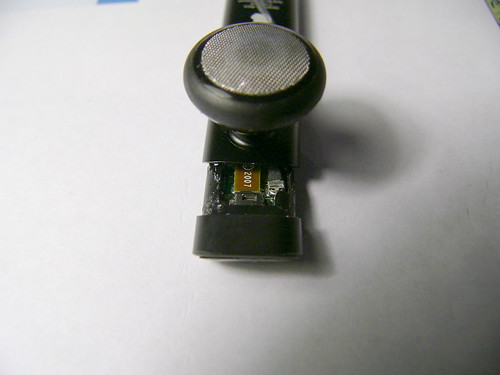
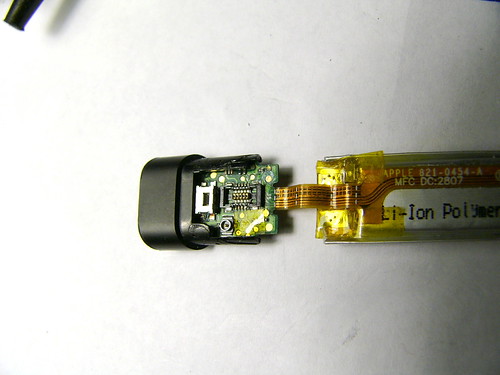
The slot for the microphone is tiny. It’s the small black rubber bit you can see peeping out from behind the connector
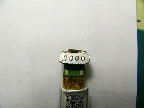
Here’s a better view
So, the whole thing consists of four really tiny circuit boards – two in the earpiece, one for the LED and switch, and one near the microphone and connector. It is an amazingly well designed feat of miniaturisation. Kudos to the team that designed it.